Loading

Voltage transformation
Distribution and power transformers, dry type and oil-immersed, isolation and special-purpose units, specified against your electrical system rather than picked off a rate list.
9 types · IS:1180 · IS:2026
The range
Plant supply
Steps incoming supply down to the utilisation voltage your plant actually runs on, the workhorse at the boundary between the utility and your distribution board.
Substation duty
For higher-capacity systems and substation duty, where the transformer is sized around fault levels and system studies rather than connected load alone.
No transformer oil. Specified where an indoor installation, a basement, or the project's fire-safety brief rules out a liquid-filled unit.
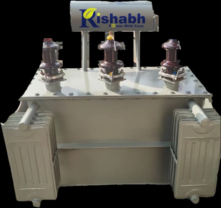
Insulating oil carries heat away from the windings, which is why this remains the standard choice for outdoor, utility and industrial distribution duty.
Galvanic separation between primary and secondary, used where the load needs to be electrically decoupled from the supply rather than simply re-rated.
Built for the harmonic content and switching stress that solar inverters and variable-frequency drives put back into the winding.
Ferroresonant CVTs hold output within a tight window without moving parts, suited to small, critical loads that must never see a sag.
Small-capacity units feeding control circuits, panel instrumentation, machine tools and lighting circuits at a reduced voltage.
Furnace, rectifier, auto and application-specific designs, built against the winding configuration and duty cycle your process demands.
How we quote
Dry vs oil
Insulation & cooling
Dry: Solid insulation, air-cooled by design
Oil: Insulating oil provides insulation and carries heat
Typical installation
Dry: Often specified indoors, in basements and occupied buildings
Oil: Common outdoors, and in utility and industrial yards
Fire & site brief
Dry: No transformer oil on site
Oil: Oil containment and clearances need planning
Maintenance
Dry: Largely inspection-based, design dependent
Oil: Adds oil testing and level checks over its life
Selected on
Dry: Site constraints, load and project specification
Oil: Site constraints, load and project specification
FAQ
A transformer is a static electrical machine that transfers energy between two or more circuits by electromagnetic induction, changing voltage and current levels in the process without changing frequency. It has no rotating parts: a magnetic core, a high-voltage winding, a low-voltage winding and an insulation system do all the work.
Alternating current in the primary winding sets up an alternating magnetic flux in the core. That flux links the secondary winding and induces a voltage in it. The ratio between the number of turns on each winding sets the ratio between the voltages, so a winding with fewer turns delivers a lower voltage at a proportionally higher current.
A power transformer generally sits in transmission and substation duty at higher capacity and voltage, and is designed to run near full load at high efficiency. A distribution transformer sits closer to the consumer, steps voltage down to utilisation levels, and spends its life on a load that varies through the day, so it is designed around good efficiency across a wide load range, not just at peak.
An oil-immersed transformer uses insulating oil for both insulation and heat transfer. A dry type transformer uses solid insulation and is cooled by air, so there is no transformer oil on site. Dry type units are often specified for indoor and occupied-building installations, while oil-immersed units remain the common choice outdoors and in industrial yards. Which one suits a project depends on the site, the load and the specification, not on one being better than the other.
Distribution transformers are grouped into energy-efficiency levels according to the losses the applicable standard permits at a given rating. A higher level means tighter permitted losses, which usually means more or better core and winding material, a higher purchase price, and lower losses over the life of the unit. Which level applies to a particular transformer depends on its rating, its design and the regulations in force at the time of supply.
Level 1 and Level 2 are energy-efficiency classifications for distribution transformers, defined by the maximum losses allowed at a given rating. Level 2 is the tighter of the two. Because the Indian efficiency framework is revised periodically, the level applicable to your transformer should be confirmed against the regulations current at the time of order rather than assumed from an older tender document.
Start from the actual maximum demand rather than the sum of every nameplate on site, then add realistic headroom for load you intend to connect later. Motor starting current, harmonic loading from drives and inverters, load unbalance, ambient temperature and duty cycle all affect the rating you need. An oversized transformer runs at poor loading and wastes no-load losses continuously. An undersized one runs hot and ages its insulation early.
Transformer losses fall into two groups. No-load losses, also called iron or core losses, occur whenever the transformer is energised regardless of load. Load losses, also called copper losses, rise with the square of the current drawn. Total losses at a given loading determine both the efficiency figure and the heat the cooling arrangement must remove.
A vector group describes how the windings are connected and the phase displacement between primary and secondary. In Dyn11, D is a delta-connected high-voltage winding, y is a star-connected low-voltage winding, n means its neutral is brought out, and 11 indicates the low-voltage side leads by 30 degrees. It matters because transformers intended to run in parallel must share a compatible vector group.
An off-circuit tap changer, OCTC, can only be moved with the transformer de-energised, so it is used to trim for a supply voltage that sits consistently high or low. An on-load tap changer, OLTC, changes taps while the transformer is carrying load, which is what you need when the incoming voltage moves through the day and the output has to be held steady without an interruption.
An isolation transformer separates a load from the supply galvanically, so there is no direct metallic path between the two circuits. It is specified where that separation itself is the requirement: breaking earth loops, containing fault current paths, or feeding equipment whose reference must float relative to the incoming supply, rather than where the aim is simply to change voltage.
Routine tests are performed on every unit, and type test certificates for the design are provided against the applicable standard for that product and rating. Where a project requires third-party inspection or witnessed testing, tell us at the enquiry stage so it is built into the schedule and the price rather than added afterwards.
Transformers
Voltage transformation
Distribution and power transformers, dry type and oil-immersed, isolation and special-purpose units, specified against your electrical system rather than picked off a rate list.
9
Transformer Types
Dry & Oil
Cooling Arrangements
Routine + Type
Tested & Certified
A transformer is a static electrical machine that moves energy between circuits by electromagnetic induction, changing the voltage and current levels but not the frequency. No rotating parts are involved: a magnetic core, a high-voltage winding, a low-voltage winding and an insulation system do all of the work, which is why a well-built transformer can run for decades with little more than inspection.
Every transformer is specified against the standard that governs its type and rating: IS:1180 for distribution transformers, IS:2026 for power transformers. Routine tests are done on every unit and type test certificates cover the design. Where a project needs witnessed testing or third-party inspection, say so at enquiry and it goes into the schedule and the price instead of becoming an argument later.
The range
Capacity, voltage class and cooling arrangement are set on the quotation, against your single-line diagram and site conditions. What follows is the shape of the range, not a price list.
Plant supply
Steps incoming supply down to the utilisation voltage your plant actually runs on, the workhorse at the boundary between the utility and your distribution board.
Governed by IS:1180
Substation duty
For higher-capacity systems and substation duty, where the transformer is sized around fault levels and system studies rather than connected load alone.
Governed by IS:2026
Built to purpose
No transformer oil. Specified where an indoor installation, a basement, or the project's fire-safety brief rules out a liquid-filled unit.
Insulating oil carries heat away from the windings, which is why this remains the standard choice for outdoor, utility and industrial distribution duty.
Galvanic separation between primary and secondary, used where the load needs to be electrically decoupled from the supply rather than simply re-rated.
Built for the harmonic content and switching stress that solar inverters and variable-frequency drives put back into the winding.
Ferroresonant CVTs hold output within a tight window without moving parts, suited to small, critical loads that must never see a sag.
Small-capacity units feeding control circuits, panel instrumentation, machine tools and lighting circuits at a reduced voltage.
Furnace, rectifier, auto and application-specific designs, built against the winding configuration and duty cycle your process demands.
Comparison
This is the question most transformer enquiries actually turn on, and there is no universally correct answer. The site decides it.
| Factor | Dry Type | Oil-Immersed |
|---|---|---|
| Insulation & cooling | Solid insulation, air-cooled by design | Insulating oil provides insulation and carries heat |
| Typical installation | Often specified indoors, in basements and occupied buildings | Common outdoors, and in utility and industrial yards |
| Fire & site brief | No transformer oil on site | Oil containment and clearances need planning |
| Maintenance | Largely inspection-based, design dependent | Adds oil testing and level checks over its life |
| Selected on | Site constraints, load and project specification | Site constraints, load and project specification |
Efficiency & losses
Distribution transformers are grouped into energy-efficiency levels (Level 1 and Level 2 among them) according to the losses the applicable standard permits at a given rating. A higher level means tighter permitted losses, which usually means more or better core and winding material, a higher price on the purchase order, and lower losses every hour the transformer is energised for the next twenty years.
The honest way to decide is to cost the losses, not just the unit. No-load losses run whenever the transformer is energised, regardless of whether your plant is working. Load losses rise with the square of the current you draw. On a transformer that stays energised around the clock at moderate loading, the no-load figure usually dominates the lifetime bill, and that is exactly the case where paying for a higher efficiency level pays back.
Because the Indian efficiency framework is revised from time to time, we confirm the level applicable to your rating against the regulations in force when the order is placed, rather than carrying forward a figure from an older tender document.
Selection
A transformer should be chosen against the whole electrical system, not capacity alone. These are the factors we work through on an enquiry:
One accountable team
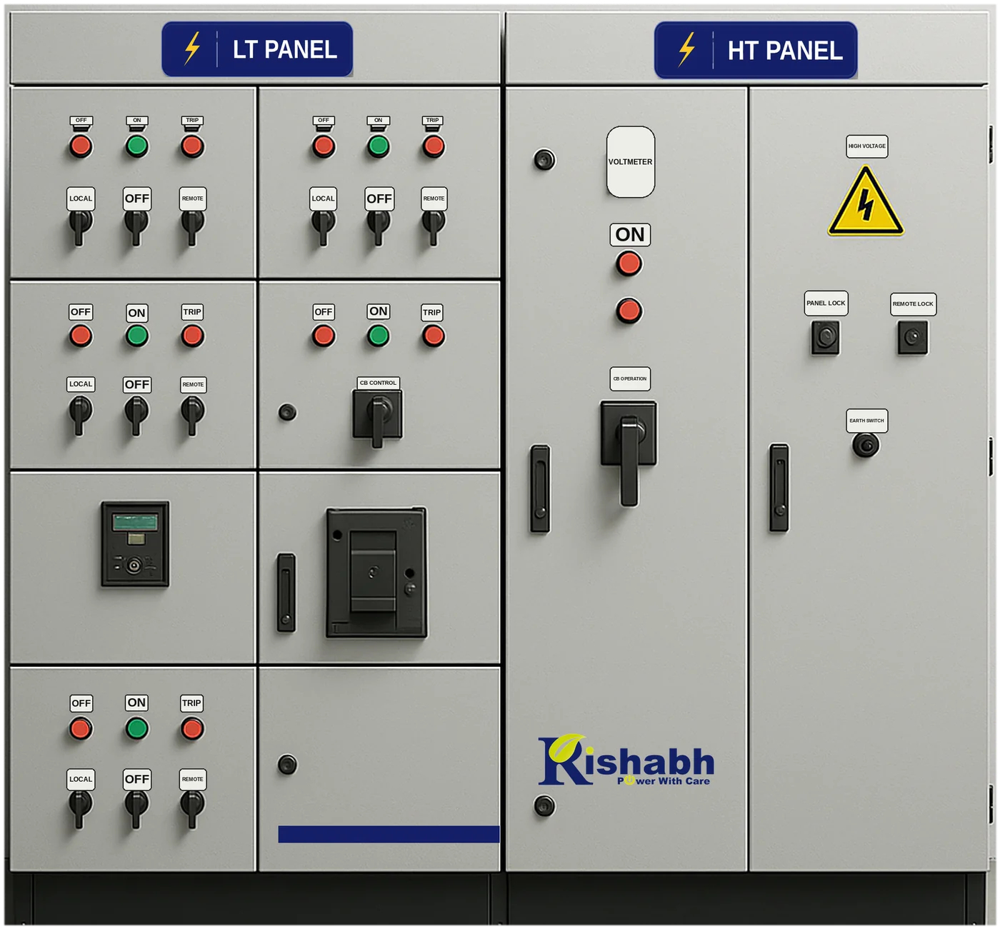
On the high-voltage side it needs switching, isolation and protection. On the low-voltage side it needs a panel to distribute what it delivers. Buy those three from three suppliers and every mismatch (protection coordination, cable sizes, busbar ratings, who tests what) becomes your problem to referee on site.
We quote the transformer, the HT/VCB panel and the LT distribution panel as one electrical system, and where a generator backs it up, the changeover between them too.
See the panel rangeQuestions