Loading

Panels & switchgear
APFC, LT and distribution, HT/VCB, AMF, ATS and synchronising panels, designed against your single-line diagram and tested before dispatch.
6 families · ATS frames 16–3200 A
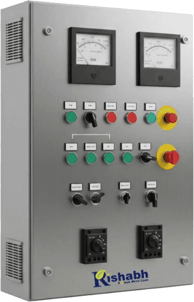
Six families
Automatic power factor correction: capacitor steps switched by a controller that watches your power factor continuously.
Low-tension receiving, switching, protection, metering and distribution: PCC, MCC, MDB and SMDB boards to your single-line diagram.
Medium-voltage switchgear built around a vacuum circuit breaker, with the protection, interlocking and metering the utility expects.
Auto Mains Failure: senses the outage, starts the genset, transfers the load, and reverses all of it when mains returns.
Automatic transfer switches from 16 A to 3200 A across five frame sizes, transferring load between two designated sources.
Two or more gensets brought onto a common bus in phase, sharing load, for sites whose demand outgrew a single set.
How they are built
FAQ
An electrical control panel is an enclosure that houses the switching, protection, control, monitoring and distribution equipment for part of an electrical system. Depending on what it is built to do, it may contain circuit breakers, contactors, relays, controllers, metering, busbars and protection devices. All of it is assembled, wired and tested as one unit so the system behaves predictably when something goes wrong.
An APFC panel (Automatic Power Factor Correction panel, also called a PFC panel) improves the power factor of an installation by switching capacitor steps in and out automatically as the load changes. A controller measures the power factor continuously and brings in only as much correction as the present load needs, rather than leaving a fixed bank connected regardless of demand.
Inductive loads such as motors, welding sets and transformers draw reactive current that does no useful work but still has to be carried by your cables, switchgear and transformer. Correcting the power factor reduces that circulating current, which frees up capacity in the existing installation and, on tariffs with a power factor penalty or incentive, changes what you pay each month.
An LT panel is a low-tension panel: it receives low-voltage supply from a transformer or generator and switches, protects, meters and distributes it to downstream circuits. It is the panel between the incoming supply and the rest of your plant, and it is where protection is coordinated so a fault in one feeder does not take out the whole installation.
They overlap, and in everyday use the terms are often swapped. Strictly, LT describes the voltage level (low tension) while distribution describes the job the panel does, which is dividing incoming power among outgoing circuits. A main LT panel usually both receives and distributes, and the smaller boards downstream of it are distribution boards. In tender language you will also see PCC, MCC, MDB and SMDB used for particular roles.
PCC is a Power Control Centre, the main incoming LT panel fed from the transformer or generator. MCC is a Motor Control Centre, an LT panel dedicated to starting and protecting motors. MDB is a Main Distribution Board fed from the PCC, and SMDB is a Sub Main Distribution Board fed from the MDB to serve a floor, zone or section. They describe roles within one distribution hierarchy rather than four unrelated products.
An HT panel is high-tension switchgear used to switch, isolate, protect and distribute power at medium voltage, typically where the utility supply arrives before it reaches a transformer. Because it operates above low voltage, interlocking, earthing arrangements and protection coordination are central to the design rather than optional extras.
VCB stands for Vacuum Circuit Breaker. A VCB panel is an HT panel that uses a vacuum circuit breaker as its switching and protection device. The contacts open inside a sealed vacuum interrupter, where the absence of any medium to ionise means the arc extinguishes very quickly at current zero, which is why vacuum breakers dominate medium-voltage switching and need little maintenance over a long service life.
The voltage level, and everything that follows from it. An HT panel handles medium-voltage supply upstream of the transformer, using vacuum circuit breakers, protection relays and strict interlocking. An LT panel works downstream at utilisation voltage, using moulded-case and air circuit breakers to feed the plant. On most industrial sites both are present, with a transformer between them.
An AMF panel (Automatic Mains Failure) watches the incoming mains supply, and when it fails, starts the generator, waits for healthy voltage and frequency, and transfers the load across. When mains returns and proves stable, it transfers back and shuts the generator down through its cooling cycle. No operator has to be present for any of it.
An ATS panel (Automatic Transfer Switch) transfers a load between two designated power sources according to its configured control scheme. The transfer switch itself is the mechanism that makes and breaks the connection, with mechanical interlocking so the two sources can never be paralleled accidentally.
They are related but not interchangeable. An ATS is the switching mechanism that moves load between two sources. AMF is the control function that detects mains failure and manages the generator: start, healthy-voltage check, transfer, return and stop. A complete generator changeover usually contains both, and on smaller systems they are built into one panel, which is why the terms get used loosely. What a given panel actually does depends on its controller and system architecture.
A synchronising panel brings two or more generators onto a common bus and keeps them running in step, matching voltage, frequency and phase angle before closing each breaker, then sharing load between the sets. It lets a site add capacity in stages, run only as many sets as the present load needs, and take one set off for maintenance without going dark.
Start from your single-line diagram and load list rather than a panel size. What voltage arrives, what has to be fed, what the maximum demand is, which loads are motors, how protection should be graded, what metering the utility or your energy team needs, and whether a generator is involved. Send us that and we will come back with the panel configuration, the switchgear selection and the price.
Effectively every panel is. Panels are designed against your single-line diagram and site constraints: enclosure dimensions and mounting, ingress protection, busbar sizing, cable entry direction, metering and communication requirements, and the switchgear brand your consultant has specified. Standard sizes exist as starting points, not as the finished article.
Control Panels
Fabricated in-house · Ghaziabad
APFC, LT and distribution, HT/VCB, AMF, ATS and synchronising panels, designed against your single-line diagram, fabricated on our own line at Ghaziabad, and tested before dispatch. Switchgear from C&S, Schneider, LK and HPL.
6
Panel Families
16–3200A
ATS Frame Range
C&S · Schneider
LK · HPL
Approved Switchgear
The definition
An electrical control panel is an enclosure holding the switching, protection, control, monitoring and distribution equipment for part of an electrical system: breakers, contactors, relays, controllers, metering, busbars and protection devices, assembled and wired as one unit so the system behaves predictably when something goes wrong. What separates a good panel from a cheap one is not the box: it is whether the protection is graded properly, the busbars are rated for the fault level, and someone tested it before it left the works.
The range, in six families
Automatic power factor correction: capacitor steps switched by a controller that watches your power factor continuously.
Low-tension receiving, switching, protection, metering and distribution: PCC, MCC, MDB and SMDB boards to your single-line diagram.
Medium-voltage switchgear built around a vacuum circuit breaker, with the protection, interlocking and metering the utility expects.
Auto Mains Failure: senses the outage, starts the genset, transfers the load, and reverses all of it when mains returns.
Automatic transfer switches from 16 A to 3200 A across five frame sizes, transferring load between two designated sources.
Two or more gensets brought onto a common bus in phase, sharing load, for sites whose demand outgrew a single set.
Power factor correction
An APFC panel (Automatic Power Factor Correction, also called a PFC panel) improves the power factor of an installation by switching capacitor steps in and out automatically as the load changes. A controller measures power factor continuously and brings in only the correction the present load needs, instead of leaving a fixed bank connected whether the plant is running or idle.
Why it matters: motors, welding sets and transformers draw reactive current that does no useful work but still has to be carried by your cables, switchgear and transformer. Pull the power factor back toward unity and that circulating current drops, which frees up capacity you have already paid for, and on tariffs with a power factor penalty or incentive, changes the monthly bill.
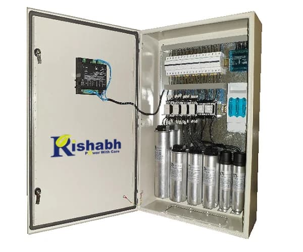
Capacitor bank, duty contactors and the power factor controller that decides which steps come in.
Low tension
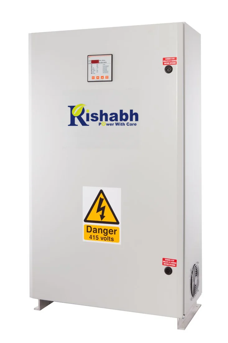
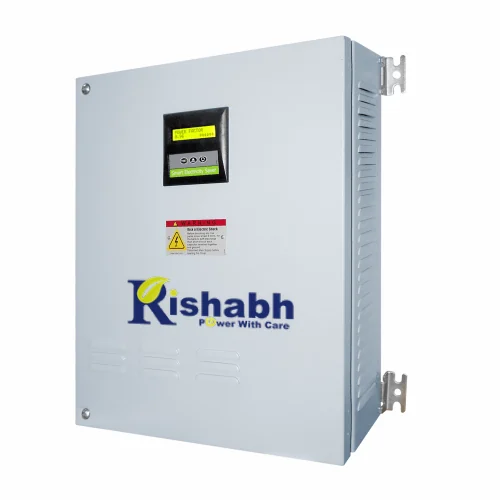
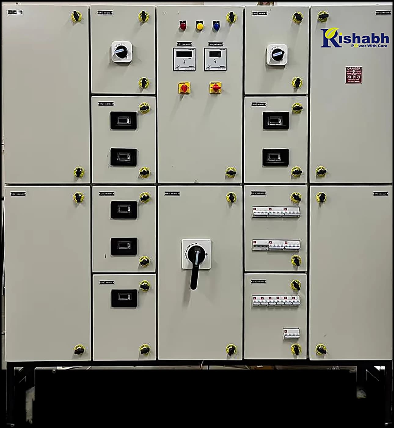
An LT panel is a low-tension panel: it receives low-voltage supply from a transformer or generator, then switches, protects, meters and distributes it to the circuits downstream. It sits between the incoming supply and the rest of your plant, and it is where protection gets graded so a fault in one feeder trips that feeder, not the whole installation.
LT panel and distribution panel are used interchangeably in practice. Strictly, LT names the voltage level and distribution names the job: dividing incoming power among outgoing circuits. In tender language the same hierarchy appears as PCC, MCC, MDB and SMDB:
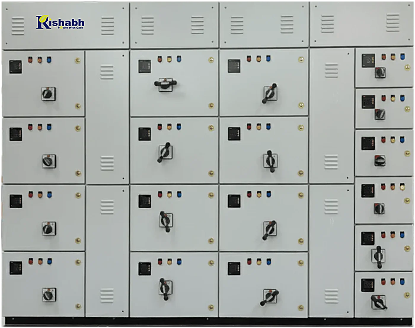
A multi-cubicle LT distribution panel, each feeder metered, switched and protected on its own.
High tension
An HT panel is high-tension switchgear that switches, isolates, protects and distributes power at medium voltage, typically where the utility supply lands on your site, upstream of the transformer. Because it works above low voltage, interlocking, earthing and protection coordination are central to the design rather than optional extras.
VCB stands for Vacuum Circuit Breaker, and a VCB panel is an HT panel built around one. The contacts part inside a sealed vacuum interrupter where there is no medium to ionise, so the arc extinguishes very quickly at the first current zero. That is why vacuum breakers dominate medium-voltage switching and why they ask so little maintenance across a long life.
An HT panel almost always arrives with a transformer and an LT panel either side of it. We quote all three as one system, so protection grading and busbar ratings are one team's responsibility: ours.
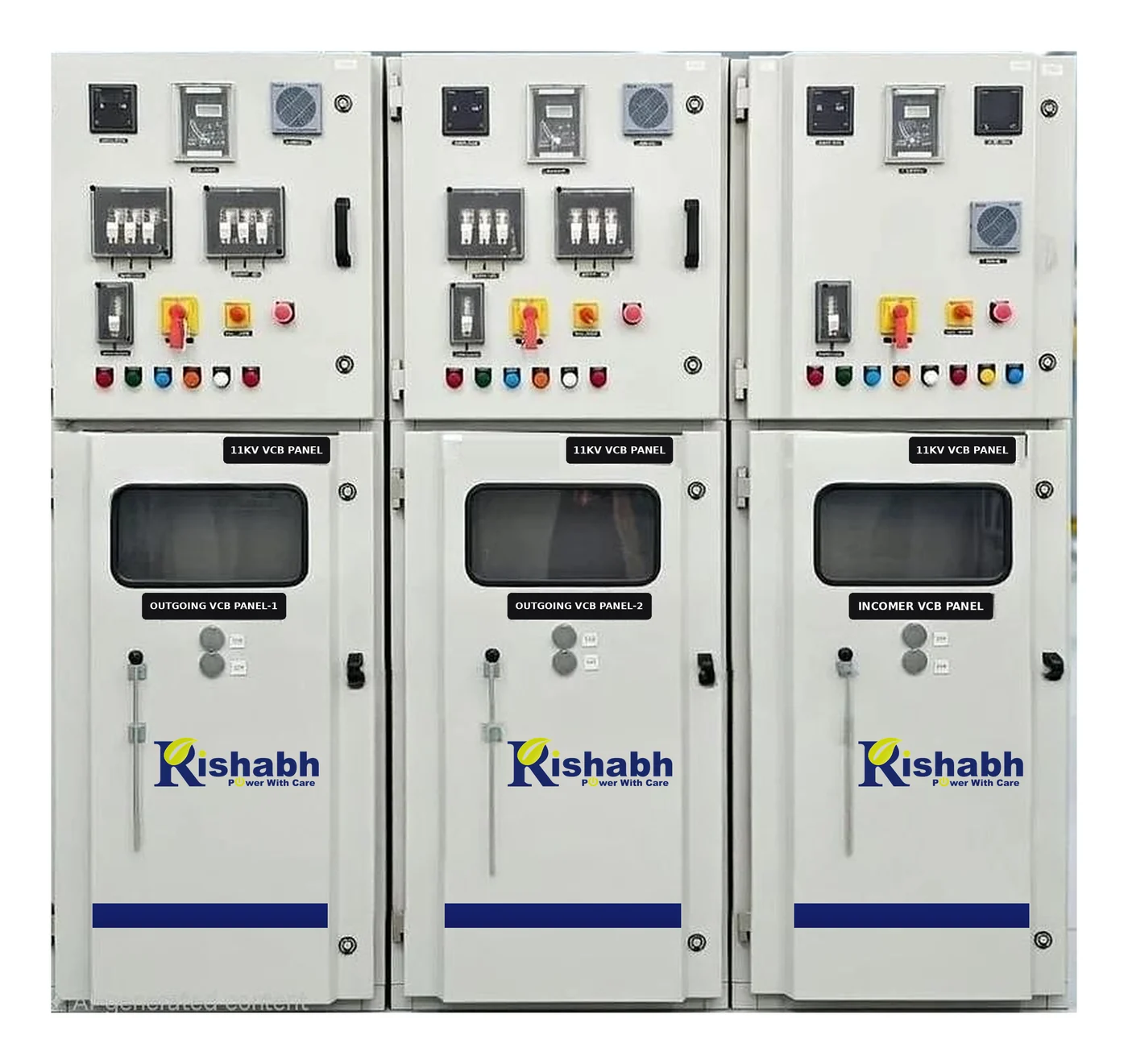
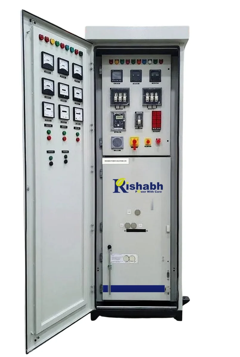
Door open: metering on the fascia, protection and control equipment inside.
Changeover & transfer
The two get used as if they were the same product, and on a small system they often live in one panel. They are different things, and the distinction matters when someone else has written the specification.
Automatic Mains Failure
The panel watches the incoming mains, and when it fails it starts the generator, waits for healthy voltage and frequency, and transfers the load across. When mains returns and proves stable, it transfers back and shuts the set down through its cooling cycle. Nobody has to be on site for any of it. AMF is a control function, and on our gensets it runs on Deep Sea Electronics controllers.
Automatic Transfer Switch
The ATS is the mechanism that moves load between two designated sources, mechanically interlocked so the two can never be paralleled by accident. Our catalogued YES1 series runs from 16 A to 3200 A across five frame sizes.
YES1 specificationsPut simply: the ATS is the switch, AMF is the intelligence that decides when to throw it and what to do with the generator either side of the transfer. A complete changeover system usually contains both, but what any specific panel does depends on its controller and the system architecture around it, which is worth confirming rather than assuming.
Generator-side panels
Two panels that only exist because of the generator they are wired to: one that parallels sets, one that runs a single set.
Multiple sets
A synchronising panel brings two or more generators onto a common bus and holds them in step: matching voltage, frequency and phase angle before closing each breaker, then sharing load between the sets. It lets a site add capacity in stages, run only as many sets as the present load justifies, and take one set out for maintenance without going dark. Sizing and load-sharing scheme are set against your demand profile.
Single set
The genset's brain: Deep Sea Electronics controllers, protection relays, metering and start/stop logic, built and load-tested with the set they control. Every Rishabh genset ships with a panel we built ourselves, which is why the controller settings match the alternator and engine instead of being dialled in on site.
How they are built
Panels are designed against your single-line diagram and load list, fabricated on the same Ghaziabad line that builds our acoustic enclosures, and tested before they leave. Switchgear comes from C&S, Schneider, LK and HPL, and where a consultant has specified a particular make, we build to that specification rather than substituting quietly.
What we need from you to quote: the single-line diagram if you have one, the load list if you do not, the incoming voltage, and any metering or communication requirement. What you get back is the panel configuration, the switchgear selection, the testing scope and a delivery date.
Existing panel giving trouble? Our service team repairs and replaces control panels on generators of any brand.
Questions